Chapter 3. Introduction to clustering, segmentation and connected components
In this tutorial we’ll create an application that demonstrates how
an image can be broken into a number of regions. The process of
separating an image into regions, or segments, is called
segmentation. Segmentation is a
widely studied area in computer vision. Researchers often try to
optimise their segmentation algorithms to try and separate the
objects in the image from the
background.
To get started, create a new OpenIMAJ project using the Maven
archetype, import it into your IDE, and delete the sample code from
within the generated main() method of the
App class. In the main()
method, start by adding code to load an image (choose your own
image):
MBFImage input = ImageUtilities.readMBF(new URL("http://..."));
To segment our image we are going to use a machine learning
technique called clustering.
Clustering algorithms automatically group similar things together.
In our case, we’ll use a popular clustering algorithm called
K-Means clustering to group
together all the similar colours in our image. Each group of similar
colours is known as a class. The
K-means clustering algorithm requires you set the number of classes
you wish to find a priori (i.e.
beforehand).
![[Tip]](images/tip.png) |
K-means Clustering |
|
K-Means initialises cluster centroids with randomly selected data points and
then iteratively assigns the data points to their closest cluster and updates
the centroids to the mean of the respective data points.
|
Colours in our input image are represented in
RGB colour space; that is each
pixel is represented as three numbers corresponding to a red, green
and blue value. In order to measure the similarity of a pair of
colours the “distance” between the colours in the
colour space can be measured. Typically, the distance measured is
the Euclidean distance.
Unfortunately, distances in RGB colour space do not reflect what
humans perceive as similar/dissimilar colours. In order to
work-around this problem it is common to transform an image into an
alternative colour space. The Lab colour
space (pronounced as separate letters, L A B) is
specifically designed so that the Euclidean distance between colours
closely matches the perceived similarity of a colour pair by a human
observer.
![[Tip]](images/tip.png) |
Euclidean Distance |
|
The Euclidean distance is the straight-line distance between two points. It is named after the "Father of Geometry", the
Greek mathematician Euclid.
|
To start our implementation, we’ll first apply a colour-space
transform to the image:
input = ColourSpace.convert(input, ColourSpace.CIE_Lab);
We can then construct the K-Means algorithm:
FloatKMeans cluster = FloatKMeans.createExact(2);
The parameter (2) is the number of clusters or classes we wish the algorithm to generate. We can optionally provide a
second integer argument that controls the maximum number of iterations of the algorithm (the default is 30 iterations if we
don't specify otherwise).
![[Tip]](images/tip.png) |
Tip |
|
There are a number of different static factory methods on the
FloatKMeans class, as well as constructors that allow
various flavours of the K-Means algorithm to be instantiated. In
particular, the FloatKMeans.createKDTreeEnsemble(int)
method creates an approximate K-means implementation
using a technique based on an ensemble of KD-Trees. The approximate
algorithm is much faster than the exact algorithm
when there is very high-dimensional data; in this case, with only
three dimensions, the approximate algorithm is not required.
All the OpenIMAJ K-Means implementations are multithreaded and automatically
takes advantage of all the processing power they can obtain by default.
This behaviour can of course be controlled programatically however.
|
The FloatKMeans algorithm takes its input as an array of
floating point vectors (float[][]). We can
flatten the pixels of an image into the required form using the
getPixelVectorNative() method:
float[][] imageData = input.getPixelVectorNative(new float[input.getWidth() * input.getHeight()][3]);
The K-Means algorithm can then be run to group all the pixels into
the requested number of classes:
FloatCentroidsResult result = cluster.cluster(imageData);
Each class or cluster produced by the K-Means algorithm has an
index, starting from 0. Each class is represented by its centroid
(the average location of all the points belonging to the class). We
can print the coordinates of each centroid:
float[][] centroids = result.centroids;
for (float[] fs : centroids) {
    System.out.println(Arrays.toString(fs));
}
Now is a good time to test the code. Running it should print the
(L, a, b) coordinates of each of the classes.
We can now use a HardAssigner to assign each
pixel in our image to its respective class using the centroids
learned during the FloatKMeans. This is a
process known as classification.
There are a number of different HardAssigners,
however, FloatCentroidsResult has a method called
defaultHardAssigner() which will return an
assigner fit for our purposes. HardAssigners have
a method called assign() which takes a vector
(the L, a, b value of a single pixel) and returns
the index of the class that it belongs to. We’ll start by creating
an image that visualises the pixels and their respective classes by
replacing each pixel in the input image with the centroid of its
respective class:
HardAssigner<float[],?,?> assigner = result.defaultHardAssigner();
for (int y=0; y<input.getHeight(); y++) {
    for (int x=0; x<input.getWidth(); x++) {
        float[] pixel = input.getPixelNative(x, y);
        int centroid = assigner.assign(pixel);
        input.setPixelNative(x, y, centroids[centroid]);
    }
}
We can then display the resultant image. Note that we need to
convert the image back to RGB colour space for it to display
properly:
input = ColourSpace.convert(input, ColourSpace.RGB);
DisplayUtilities.display(input);
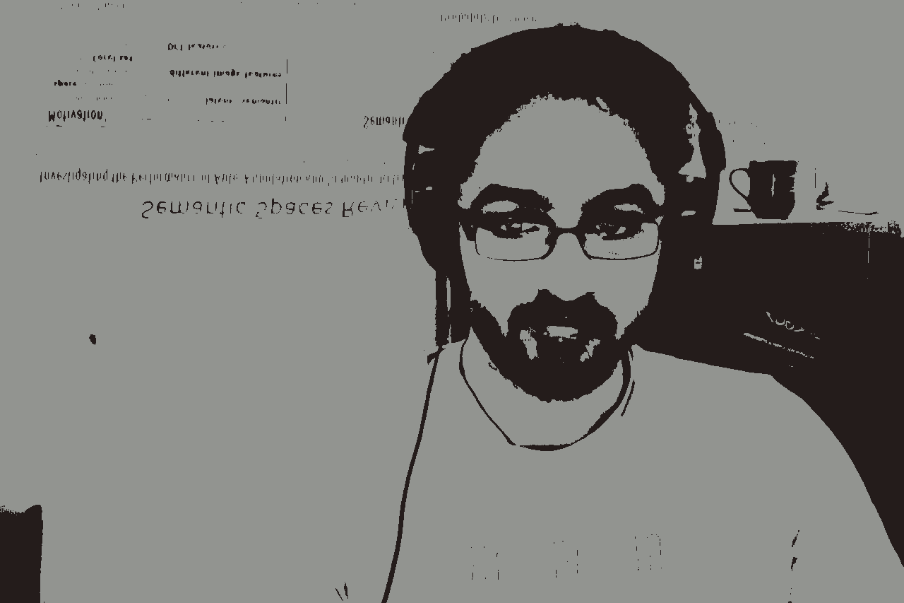
Running the code will display an image that looks a little like the
original image but with as many colours as there are classes.
To actually produce a segmentation of the image we need to group
together all pixels with the same class that are touching each
other. Each set of pixels representing a segment is often referred
to as a connected component.
Connected components in OpenIMAJ are modelled by the
ConnectedComponent class.
The GreyscaleConnectedComponentLabeler class can
be used to find the connected components:
GreyscaleConnectedComponentLabeler labeler = new GreyscaleConnectedComponentLabeler();
List<ConnectedComponent> components = labeler.findComponents(input.flatten());
Note that the GreyscaleConnectedComponentLabeler
only processes greyscale images (the FImage
class) and not the colour image (MBFImage class)
that we created. The flatten() method on
MBFImage merges the colours into grey values by
averaging their RGB values.
![[Tip]](images/tip.png) |
Tip |
OpenIMAJ also contains a class called ConnectedComponentLabeler which can only
be used on binary (pure black and white) FImages.
|
The ConnectedComponent class has many useful
methods for extracting information about the shape of the region.
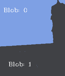
Lets draw an image with the components numbered on it. We’ll use the
centre of mass of each region to position the number and only render
numbers for regions that are over a certain size (50 pixels in this
case):
int i = 0;
for (ConnectedComponent comp : components) {
    if (comp.calculateArea() < 50)
        continue;
    input.drawText("Point:" + (i++), comp.calculateCentroidPixel(), HersheyFont.TIMES_MEDIUM, 20);
}
Finally, we can display the image with the labels:
DisplayUtilities.display(input);
3.1.1. Exercise 1: The PixelProcessor
Rather than looping over the image pixels using two for loops,
it is possible to use a PixelProcessor to
accomplish the same task:
image.processInplace(new PixelProcessor<Float[]>() {
    Float[] processPixel(Float[] pixel) {
        ...
    }
});
Can you re-implement the loop that replaces each pixel with its
class centroid using a PixelProcessor?
What are the advantages and disadvantages of using a
PixelProcessor?
3.1.2. Exercise 2: A real segmentation algorithm
The segmentation algorithm we just implemented can work
reasonably well, but is rather naïve. OpenIMAJ contains an
implementation of a popular segmentation algorithm called the
FelzenszwalbHuttenlocherSegmenter.
Try using the
FelzenszwalbHuttenlocherSegmenter for
yourself and see how it compares to the basic segmentation
algorithm we implemented. You can use the
SegmentationUtilities.renderSegments() static
method to draw the connected components produced by the
segmenter.

![[Tip]](images/tip.png)

